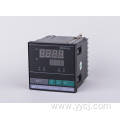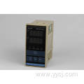

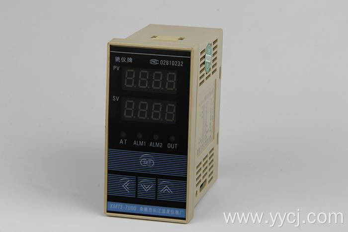
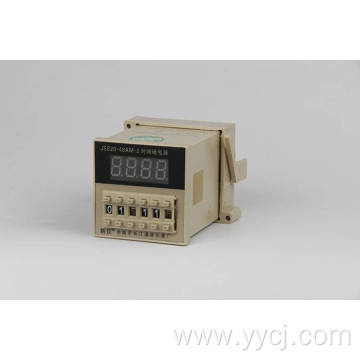
XMT-7000 Series Single Intelligent Temperature Controller
Get Latest Price| Payment Type: | T/T,Paypal |
| Incoterm: | FOB,CFR,CIF,EXW |
| Min. Order: | 2 Piece/Pieces |
| Transportation: | Ocean,Land,Air,Express |
| Port: | NINGBO,SHANGHAI, |
use:

| Payment Type: | T/T,Paypal |
| Incoterm: | FOB,CFR,CIF,EXW |
| Min. Order: | 2 Piece/Pieces |
| Transportation: | Ocean,Land,Air,Express |
| Port: | NINGBO,SHANGHAI, |
Model No.: XMT-7000 Series
Brand: CJ
Control Typel: Digita
Control Method: Electronic Type
| Selling Units | : | Piece/Pieces |
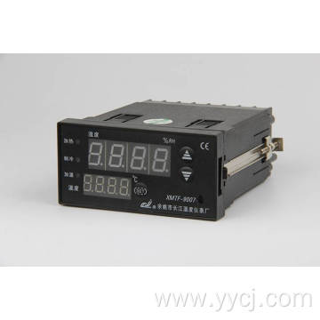
XMT*7000 Series intelligence digital temperature control instrument
Instruction Manual
Ⅰ、Product characteristic:
The core of the product adopts the up-to-date microprocessor chip.
Red and green double-bank nixie tube display the measured value and setting value.
Easy operation in the four/three keys, & fast setting in the parameter.
Control in high precision’s PID intelligent and two or three bit location check program.
Upper-bank display the measured value, & bottom-bank display the setting value under normal working conditions.
Ⅱ、Primary technical standard:
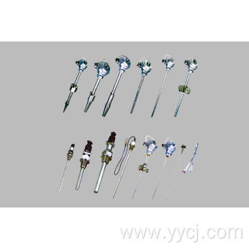
Input: Thermocouple: K、E、J、S Thermal resistance: PT100 、 CU50
Range: K(0~400℃、0~1300℃)、E(0~400℃、0~800℃)、J(0~1000℃)、 S(0~1600℃)、PT100(-100.0~200.0℃、0~600℃)、CU50(-50.0~150.0℃)Measure error: ±0.5%F.S±1byte
Silicon control trigger signal(over zero): Range≥3V, Width≥40us
The output contact potential of the relay: impedance load AC220V 5A
Input power: AC85~242V 50/60Hz
Environment: Temperature: 0 to 50℃, Humidity: ≤85%RH
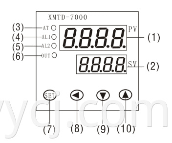
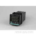
(1)PV displayIndicates the process variable (PV) with a red LED.
(2)SV displayIndicates the setting value (SV) with a green LED.
(3)AT indicator When auto tuning function is ON, a green LED lights.
(4)ALM1 indicator When ALM1 output is ON, a red LED lights.
(5)ALM2 indicator When ALM2 output is ON, a red LED lights.
(6)OUT indicator When OUT is ON, a green LED lights.
(7)Mode key (SET) Switches the setting mode and registers the setting value and selected value.(Setting value and selected value are registered by pressing the mode key.)
(8)Data shift key (<)
(9)Decrease key (∨)Decreases numeric value of the setting value
(10)rease key (∧)Increases numeric value of the setting value.
Note: XMTG-7000 only has three keys, has not Data shift key and ALM2 indicator.
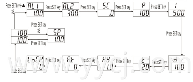
Ⅳ、Setup flow chart
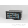
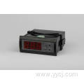
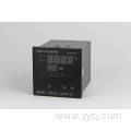
Size: XMT:160×80×125mm hole:152×76; XMTA:96×96×85mm hole: 92×92;
XMTE:48×96×85mm hole: 44×92; XMTF:96×48×85mm hole: 92×44;
XMTD:72×72×85mm hole: 68×68; XMTG:48×48×110mm hole: 44×44;
Ⅲ、Name and functions of the sections(consult)
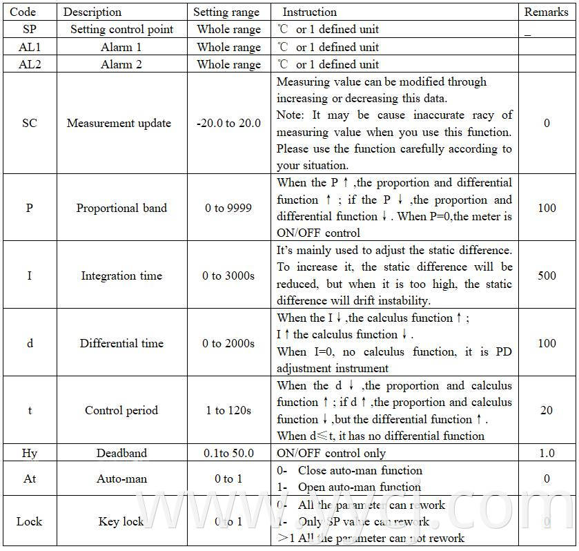
Ⅴ、Display Status(consult)
Note: 1. LC is key lock. It can rework all parameter when LC is 0. It can only rework SP value when LC is 1.
2. The no all meter have up wards parameters, only answer for correspond to function
meter have corresponding parameters.
l Connect the power, the Sensor and the external control circuit to the instrument refer to the connection figure. After these, turn on the power and then the instrument will at first begin to auto-test according to the program A, Band C.
A: All LEDS and all indicating lamps will be lighted to test the lighting-system whether good or not. If unlighted LED or indicating lamp were found, please stop using and transmit it to for repairation. (This procedure lasts for 0.5s)
B: The window PV (upper window) display “CJ”, the window SV is not display.
C: The window PV display model.
After the three procedures, the instrument will step into the normal measure-control state. The upper window PV display the value that the instrument is measuring and the lower window SV display the value set.
l If want to modify the value in the window SV, press the SET key 3 second when the instrument is in its normal display state, then the window PV will display “SP” and the window SV will point wink. At this moment press the key ∧ to increase the value or the key ∨ to decrease (Press the key ∧ or ∨ for a longer time to accelerate the speed of value setting). Press < key shift (like cursor). Press the key SET to certain the modified value. If no any other operation after modification, the instrument will automatically return to the normal display state and accept the modified value at the same time.
l If want to modify the value other than “SP”, press the key (SET+∧) 3 second when the instrument is in its normal display state to set the internal parameter. Please set the value in terms of the actual application. But please pay more attention to the three items “P、I、d”, these must be set by experienced engineer.
l Auto-man: the first set value is OK, after at being “1”, the “AT” indicating to it will light. The instrument begins working as the ordinary one with two control points and three states. After 3 cycles, it will certain the best PID value to the set point and store it forever unless the user’s modification or opening the “AT” function.
l The signal “HH” or “LL” in the window PV means that the sensor is out of connection or the measured value is overflow.
Ⅵ、Connection figure(consult)
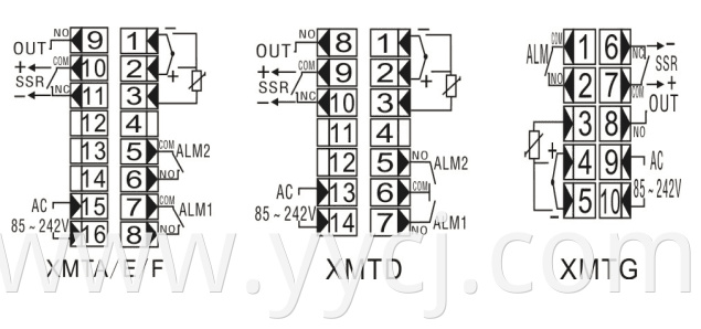
Note:The connection wire drawing only for reference,it should be subject to the attached drawing.
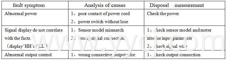
Ⅶ、Fault Analysis and Clearance
XMT*-7000 adopts advanced production process, and has the strict test before leaving factory, it improve the reliability of the meter .The usual fault is caused by the wrong operation or parameter setting .If you find the fault couldn’t be cope with, please record it,and contact with the agent or us. Sheet 7-1 is the usual fault of XMT*-7000 in the daily application:
Sheet 7-1 Common fault handling
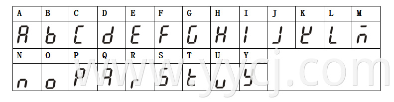
Attached 1:Statement of meter’s parameter attention letter and English letter


Contact

Send Inquiry
PRODUCTS
RELATED PRODUCTS
FOLLOW US


Privacy statement: Your privacy is very important to Us. Our company promises not to disclose your personal information to any external company with out your explicit permission.
Fill in more information so that we can get in touch with you faster
Privacy statement: Your privacy is very important to Us. Our company promises not to disclose your personal information to any external company with out your explicit permission.